Peter Lau
Bill Chun Wai Hung
Lab 10 Report
¨C 5V Power Supply
A. Describe the Set-up
The Circuit
setup is shown in figure 1.
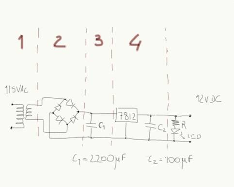
Figure 1
B. Describe Inputs
Stimuli:
The 115V ac supply from the
outlet is used as the input.
Transformer: 115Vac to 12Vac
transformer is used.
Diode: The model
for the diodes are D1N4002
C1 = 2200uF
Voltage Regulator: The model for
the Voltage Regulator is 7812, which gives an output voltage of 12V.
C2 = 100uF
Resistor: The target value of the
resistor used is 12V/20mA = 600 ohm. The resistor used during the experiment is
1k ohm.
LED =
Light Emitting Diode
C. Describe What you Observe
The LED
lit up. The experimental output voltage of the Voltage Regulator is 12.01V,
which agrees with the expected value of 12V.
D. What you can deduce
Q1) What is the maximum current that your power supply can ship to the load?
The maximum current is limited by the maximum output current of the transformer used. The transformer maximum current output of the transformer is 500mA.
The resistance of the resistor is 1k ohm, and the voltage drop across the resistor is measured to be 10.0V. So the current across the load (resistor and LED) is 10V/1k = 10mA.
The current through the ground pin is measured to be 5mA, and the current input through the left pin of the Voltage Regulator (7812) is 15mA.
____
15mA --> |7812| -- >10mA
-------
|
5mA
|
Ground
Figure 2.
The 5mA is diverted to the ground by the regulator, and this 5mA is constant regladless of the load current. In practical terms, this means that the maximum output current of the regulator is determined by the maximum current that can be drawn from the transformer. The transformer is rated at 500mA AC-RMS. This can roughly be translated to a maximum load of 500mA DC after rectification and filtering (neglecting the 5mA current).
Therefore we conclude that the maximum output current from this voltage supply is 500mA, although this figure is not exact, and is subject to a variety of other considerations such as the output ripple, and the heat dissipation limit of the voltage regulator.
Q2) Compute the minimum load that can be connected to the power supply.
Since the maximum out current is 500mA, and the output voltage is 12V. The minimum resistance of the load is R=12V/500mA = 24 ohm.
What I
am planning to do in order to claim my circuit works.
The circuit works because the output voltage is 12V, there current through the circuit is measured as stated above (Figure 2), and the LED lit up.